
The preparation of a new spare part usually starts with measuring. However, many office chairs have this part made of plastic, so we can safely assume that the forces applied to these parts aren’t extreme. We cannot place anything under the screw’s head, because the screw head should fit the hexagonal opening perfectly. We can place a metal washer between the chair and the printed part, which will help to distribute the force more evenly. The most stressed part will be directly under the screw’s head and between the printed part and the metal part of the chair. The printed part will be subjected to compression, which is something that 3D printed objects can withstand very well. By tightening the screw, we can regulate the force used to hold the back of the chair in place. The blue shape represents a side view of a cylinder with a hole for the screw in the middle. Here’s how it should look from the side in a cross-section: A 3D printed part which is easy to print and it’s sturdy at the same time. Therefore, we will not create a 1:1 replica, but simply a part that will have the same function. We have no idea how the part looked before.
OPENSCAD CHAMFER PLUS
We need to create a spare part for the chair, a knob that will hold the screw in place, plus it will enable me to tighten the screw by hand. I decided to fix this problem, quickly and efficiently.įast forward about two years, and here I am, coming up with a plan! The plan But the screw itself is too thin and doesn’t hold the back of the chair properly. To be honest, I don’t really care about visual aesthetics, because you can’t usually see the underside of the chair anyway. The plastic knob on the underside of one of our office chairs broke in half, so now only a bare screw remains: The underside of a cheap office chair usually looks like this:

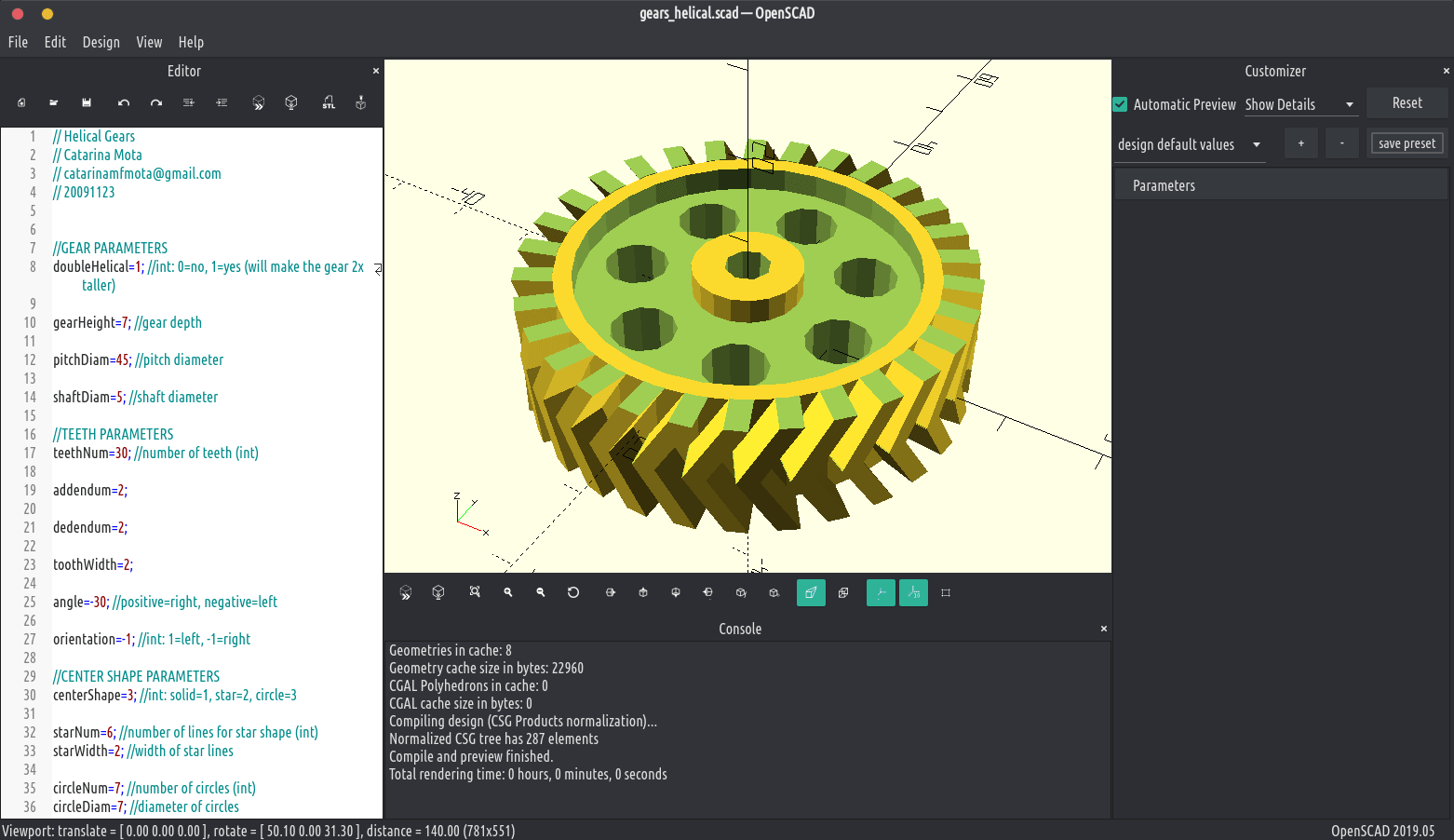
And don’t worry, it’s not that difficult! The problem For instance, you can create a general shape, like a gear, and then you can easily change its size or number of its teeth just by changing a variable. What’s so great about this? One of the biggest benefits is that OpenSCAD allows you to parameterize items. This freeware application might seem a bit frightening to new users because it takes a different approach to 3D modeling – it allows you to create 3D objects by programming. However, this time we won’t be using Fusion360 or similar software.
OPENSCAD CHAMFER HOW TO
What if you need a custom-made model? Today, we’ll look at how to tackle a quite common problem: creating a spare part from scratch. Once a Body exists, features can be attached to it using the Body's addObject() method.How do you 3D print something? Well, that’s easy: get an STL model, load it into a slicer app, generate a G-code, upload it to a 3D printer and that’s it! But what if you can’t find the desired STL file in an online repository. See PartDesign Body for the general information on adding a Body. See Part Feature for the general information on adding objects from the Python console. See also: FreeCAD Scripting Basics, and scripted objects.

The PartDesign::Feature objects are used to build parametric 3D solids, and thus are derived from the basic Part::Feature object. Simplified diagram of the relationships between the core objects in the program.

To learn more about creating solid objects with the PartDesign Workbench see feature editing.Īlmost all tools in the PartDesign Workbench are meant to add features to a PartDesign Body. The word "feature" refers to the operation itself, and also to the resulting solid after that operation. There are many types of features which can add or remove volume from an initial solid. For example, each time you add a solid box with PartDesign AdditiveBox, you add a feature when you add a chamfer to an edge with PartDesign Chamfer, you add another feature when you cut a hole using a sketch and PartDesign Pocket, you add another feature.įeature editing in a PartDesign Body with three sequential features. A PartDesign Feature refers to a "step" in the modelling process that happens inside of a PartDesign Body.


 0 kommentar(er)
